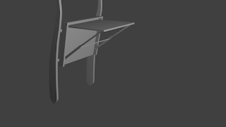
Schematic of car backseat tray
- Four relays .
- Two push buttons
- one click button
- DC supply
 |
| schematics of car tray system |
Connect motor while table is fully opened and switch two is pressed . shown under the top in 3d view of car tray table and second from top to bottom in schematic.
- Connect n/c pin of relay 2 to positive and n/c pin of relay 3 to negative.
- Connect n/o pin of rely 2 to negative and n/o pin of relay 3 to positive.
- Output from common pins of both relays is connected to dc geared motor.
When click switch is pressed down relay two will be operated too making other terminal negative motor will rotate in opposite direction . switch 3 will be released as table top rotate away making no difference on rotation as both relays are operated by click switch too. Rotation will continue until switch 2 is pressed down which will operate relay 1 making it open. and relay 3 will be also in off position i.e common pin is connected to n/c pin making dc motor at same potential and stop rotation.
 |
| schematic using diode |
- You can add diodes between relays to control flow of current.
- Use resistors to limit current flow in coils of relays.
battery = dc supply from car.
next post will be similar operation using micro-controller and centralized (more than one car table trays.)


Comments
Post a Comment